The advantage is that it removes the oxide layer without scratching like sandpaper. Next, wipe with alcohol, acetone, solvent, or wash with soap, depending on your taste. Personally, I use brake cleaning spray.


Knurling. Here I will go into more detail. I don’t know whether the photoresist is too good or too new, but if you apply it to copper, you won’t be able to tear it off. Grabs to death. I did my first attempt like this. I tore off the protective film from the edge. This one is matte. Next, I applied the corner to the copper and gradually, pressing with my finger, pulled out the film. It stuck well, but there was dirt and bubbles... In short, I switched to the principle of toners. We take a two-cc syringe and fill it with plain, cold tap water. Next, tear off the protective film completely. We hold the photoresist with one hand, and with the other we pour water from the syringe onto the copper. A syringe is more convenient, since the copper is degreased and the drops roll off, and the syringe dispenses a little bit over all the copper. After wetting, apply photoresist. While the copper is wet, the photoresist moves freely over it, and the water pushes out all the debris and air. And even if something goes wrong, you can always tear it away from the copper. After adjusting from the center to the edges, using a rubber spatula, without pressing, expel the water. When all the water has come out, we begin to squeeze out the remainder with force, also from the center to the edges. The photoresist will begin to fray closer to the edges. It's OK. Pressing from the center with a spatula, it stretches quite easily and fits well.

After ironing, wipe with a napkin or toilet paper, it doesn’t matter. The main thing is to wipe it dry. Take a sheet of clean paper and fold it in half. Between the halves we put textolite with photoresist and close this sandwich.

Well, here it is, some with an iron, some with a hairdryer, personally, I with a laminator. Heat the laminator at the highest temperature. After warming up, we send our sandwich there. Attention!!! If you send it to the laminator without a sheet of paper, then the pieces of photoresist, those that stick out outside the PCB, will be wound around the hot rollers and it won’t be easy to tear it off from there.

I run it through the laminator twice to warm it up thoroughly. In the end I get something like this.


Sample. There are three options here. The first is the printing house. Well, given its absence near my house, this option immediately disappeared. The second is printing on paper using a laser printer, then clearing it with a transparency. Well, I don’t have this crap. And the last one is printing on film. The laser printer produced poor quality, or rather not bad, but a rather transparent toner. Hold over acetone vapor... Not ice for two reasons. The first is that it stinks, and they will kick me out of the house, and the second is that for some reason now acetone has been replaced with some kind of nasty thing, which leaves drops of water after evaporation. So I switched to an inkjet. Besides, I have it sharpened for photos. Lomond film was chosen for printing.

She has one drawback. The surface on which you need to print is quite sticky and any debris sticks to it, and this, as practice has shown, negatively affects the quality of the board. In short, if the distance between the tracks is 0.2 - 0.1 mm, then a speck of dust can play a bad role and create a gap between the tracks. Otherwise, this film makes excellent templates.


Oh yes, I almost forgot. The template needs to be printed inside out, that is, negative. Where to etch copper black, and where to leave it transparent. And don't forget to mirror. The important thing is that the paint should lie on the copper, and not vice versa with the paint facing up. In general, we put the template on a photoresist and all this under a UV lamp. I have it like this:

Let's take a closer look here. Lamp: model ELSM51B-Color 20W Black. As you can see in the photo, it is energy saving. Bought at Chip-Dip for 200 rubles. The distance from the lamp to the PCB is 20 cm. Taking into account the fact that glass blocks UV light, it is impossible to specifically specify the exposure time, since someone will tear 6 mm glass from a sideboard, someone 3 mm from an entrance window. I bought a photo frame made of thick wood measuring 300 by 200 from OBI. The pieces of iron and cardboard immediately went into the trash, and the 2 mm thick glass was used as a clamp. I used the frame itself to stretch the mesh for applying the solder mask. But this is a topic for another article. So I have 2 mm glass. For cargo I use two 7 Ah gel batteries. In this form, the illumination is visible for exactly two minutes from turning on the lamp to turning it off. I don’t warm up the lamp, since 20 watts is quite powerful. As a result, I get an exposed photoresist. Another advantage against ours is that after development the exposed areas darken and you can see what happens. Next we prepare the bath. The glass is COLD!!! water half a teaspoon of soda ash. The water should be at room temperature. If you take it hot, it will be like with our photoresist. All the tracks will fall off. After preparing the bath, we bathe the textolite.


If you use a brush, development will take no more than a minute. As a result, we will get this beauty.


Let's dry it and see. If something is wrong somewhere, we correct it. If we can’t fix it, we start all over again. Another plus against our photoresist. After exposure, we throw it into a solution of soda ash for 30 minutes and the photoresist will fall off on its own. I couldn’t tear off the domestic one, either with acetone or soda. In short, I threw out the damaged blanks. After all checks, we etch in an etching solution. Here it's every man for himself. Some in acid, some in vinegar, personally I prefer ferric chloride. Preferably water, otherwise anhydrous if you throw it in water it will explode :)

Well, after etching, as always, drilling and applying a solder mask, but this is the topic of the next article.


It seems like with a photoresist and that’s it, if you have any questions, write either in the comments or on the forum.
Good boards to everyone.
Great article. I did everything as written, it worked the first time. Now if only someone could write the same article about metallization :)
Some kind of game. 1. "In short, if the distance between the tracks is 0.2 - 0.1 mm, then a speck of dust can play a bad role and create a bridge between the tracks." The photoresist is negative (see below about the template). A speck of dust will prevent the track from being illuminated and the result will be a break in the track and not a short circuit. 2. “For cargo I use two 7 Ah gel batteries.” There is no HELIUM in batteries, but GEL. And it is not at all necessary that maintenance-free batteries contain gel. Gel batteries are rare. 3. "As a result, I get an exposed photoresist. Another plus against ours
Comment cut off. OK. Let's repeat. Some kind of game. 3. “In the end, I get an exposed photoresist. Another plus against ours, after development, the exposed areas darken and you can see what happens. Next, we prepare a bath. For a glass of COLD!!! water, half a teaspoon of soda ash. The water should be at room temperature If you take it hot, it will be like with our photoresist. After preparing the bath, we bathe the textolite. If you use a brush, the development will take no more than a minute.
In the end, we will get this kind of beauty." We won’t get ANYTHING. Before etching, you need to peel off the protective lavsan film from the surface of the photoresist. Regardless of the origin of the film photoresist. (import or Russia). So here it is: "Andrey 04/05/13 Excellent article. I did everything as written, it worked the first time." a lie. Miracles don't happen, it doesn't etch through the film. And if you tear off the film before exposure, the photoresist will stick to the glass. 4. "We dry it, we look. If something is wrong somewhere, we fix it. If we can’t fix it, we start all over again.
Amazing:). The photoresist has flown off - pure copper remains - now is the time to etch. Even if we assume a miracle that something (be it soda or ferric chloride) got through the un-removed protective film... For the photoresist to fly off. The humor joke about the explosion is also completely out of place. Someone might even believe it. So we need to edit this magnum opus. And in the future, don’t write a review for yourself (this is about the mythical Andrey, who did as in the article and it worked out for him :)). Read the comments from bottom to top, “stitching” together identical pieces of text.
Total. CORRECT: 1. Negative pattern. Possibly on a laser. I don’t have a jet - but everything is fine. 2. We tear off the lower matte polyethylene film. 3. Glue it and let it rest under the load. 4. We illuminate the template with paint (toner) to the photoresist.
5. After exposure - pause 30 minutes. Then we peel off the top shiny lavsan protective film and develop it in soda. In a weak solution (citric acid - a teaspoon per glass) we tan the developed. 6. Add ferric chloride a little at a time into warm water (so as not to boil) and poison it in it.
7. Pickled - in any alkali ("Mole" diluted 1:10 - 1:50 is the best). The photoresist will fly off in 10-15 minutes. 8. Wash with water (you can use liquid detergents). 9. We drill, tin, and solder parts. All. In short - we do it according to the instructions...
Dear SergeBS 1 regarding the film, describe its removal? He may suggest that you learn Russian, otherwise how will you read the article, it’s written in Russian. 2 With a battery, this is just banter for the sake of writing. What difference does it make what you press. For example, I have now replaced them with two trances. And that there are few photographs in the article. By the way, this board works and feels great. And in the end, there is a section “Write an article”, you write, and they will criticize you, then we’ll see. And anyone can shout and throw mud.
Oh yes, about the laser guy. Neither XP nor Xerox provide high-quality templates. I've tried everything. Especially if with a domestic resist, then it stupidly lights up as if there is no template at all. Maybe, of course, they sold me an old resist... And if, according to your scheme, you tear off the protective film and try to glue it, and then under the load.)))) Well, well.
Alexey, a very wonderful article. I have a great desire to do all this, first of all, buy everything I need (if you help with this, I will be very grateful). And what kind of inkjet printer did you use?
At first I had an Epson Stylus CX4300, but the head on it dried out. Now I bought an Epson L110. It is designed for constant use and the ink is poured into flasks from the side, not cartridges. According to my measurements, black paint is enough for 50 A4 sheets of solid fill. And of course ink is much cheaper. If you have any questions, write. I will definitely answer.
Hello. The article is actually good, I say this as a person who has been manufacturing boards for more than 15 years. SergeBS, why are you so upset? Write your article, businesslike. :+) And I have one question for the author: could you tell me what settings you set on the Epson L110 to print a template? Best regards, Mikhail.
Hello Mikhail. In the printer properties, select the "Advanced Settings" tab. In the "Color Correction" section, check the "Adjustments" box. The "Advanced..." button will appear; clicking on it will open the settings menu. In this menu, brightness is set to minimum, and contrast and saturation are set to maximum. Yellow color is at maximum (yellow blocks UV), and magenta and cyan are at minimum. Yes, here’s another thing: uncheck the “High printing speed” checkbox. That seems to be it.
What material/quality do you choose? In general, it’s interesting, it’s simple, I also use L100 now, and on the contrary, I removed the yellow, otherwise it refuses to dry on the template (the film is the same).
And there the quality is either automatic or manual. My material is just paper. Does it take long to dry? What kind of ink? Relatives, “Fool” or not original? This is important.
My dropdown list is full of everything. Normal, high, photo, best photo... I am now printing using Photo RPM (max dpi) with saturation turned up. It prints slowly, there are a lot of passes, but the quality is perfect. Only the yellow color takes a very long time to dry. And the ink is original, which came with the kit.
Well, basically that's it. I set it up the same way on the old one. How long does it take to dry? If it’s about 10 minutes, then you can roll out the photoresist at this time. :)
For some reason, in the space between the 0.1-0.2 mm tracks, the photoresist in soda does not work well... you have to hold it longer and help with a brush, and at the moment when this space is cleaned, in other places with thicker tracks the pads are already falling off and the tracks themselves are flying off..
Try reducing the exposure time by 10-15 seconds.
Hello, Alexey! Thanks for the article. It's funny, but I'm now making exactly the same board for exactly the same controller, only not 100 but 103 series. I am suffering with PF-VShch. And my problems are exactly the same as you described. I have already made a sheet of 30x50 (my board is 5x6cm, i.e. about 50 samples), but the result is zero. I'm not giving up yet. We don’t have any other FR in our city. :(
“Another advantage against ours: after development, the exposed areas darken and you can see what happens.” Not after development, but after exposure.
Yeah, thanks, I also suffered with this PF-VShch. I thought that was it, my hands had grown to another place. And yet I took Ordyl for a test, and everything worked out right away. Even with a template with gaps (LED printer), it turned out fine with minimal illumination.
I’m leaving this PF-Vsch in good hands))) 5 meter roll. True, the expiration date has already expired, but I think it’s okay... My protective mask has been expired for 2 years and nothing. So if anyone wants to try their luck with PF-VShch, write. Otherwise, it’s like a suitcase without a handle; you don’t need it yourself, but it’s a shame to throw it away.
There are many PCB manufacturing technologies available to hobbyists. Each has its pros and cons.
I tried the following:
At the beginning of my hobby for amateur radio, I made boards using a regular pen rod. A ball was squeezed out of the tip with a needle, and a good drawing pen was obtained. Next, a varnish of suitable viscosity was sucked in and paths were drawn with this device. Pros- necessary equipment Almost everyone has it at hand, the technology is negligible. Cons - no automation.
Then I got a laser printer and board layout programs. Experiments began on transferring the board design from a printout to textolite. There are many nuances in the technology: the quality of the translation depends on the material and structure of the paper, the temperature of the iron, the material and baking temperature of the toner, the pressure of the iron on the paper-textolite sandwich. As a result of my research, I came up with the following: HP LJ 1018 printer, we print on thin coated paper, in my case it is a gutted Upgrade magazine. We use only the original cartridge, no refills, because the toner density decreases. We sand the board with a zero polish, then transfer the print with an iron, frying at maximum, through 2 sheets of A4. And finally, under warm water, erase the paper with your finger.
Advantages of the technology: minimal time between printing and receiving the payment, no chemicals are needed, there is an incentive to read magazines. Disadvantages: instability of the technology, dependence on many factors, difficulty in obtaining large boards with small traces - they will always peel off in places, bald spots have to be retouched. With some luck, you can ruin the surface of the iron. For stability of knurling, instead of an iron, you need an expensive laminator with temperature control; ordinary cheap ones do not warm up the board, the print does not even stick.
The latest technology I mastered, which immediately showed a qualitative leap in board manufacturing - use of film photoresist...
Briefly, the technology looks like this: we make a transparent negative template with a board pattern, roll a film photoresist onto the textolite, run the sandwich through a laminator (or iron it) to fix it, put the template on the board, illuminate it with an ultraviolet lamp, peel off the lavsan and develop it.
At first glance it looks too long, but it is compensated by almost 100% result. However, to get stable results, you will have to spend a little money.
First of all, I recommend purchasing laminator. You can also roll the film with an iron, but as practice shows, due to the unevenness of the board and surface, the photoresist is often not rolled in some places and, as a result, subsequent peeling of the tracks in this place.
In METRO or AUCHAN you can buy the cheapest laminator for 800-900 rubles, but we don’t need anything better. You can also make a laminator from a stove from a printer or copier, but this is not for everyone.
Absolutely necessary printer. I use laser, but inkjet will also work. It is highly advisable to use cartridges for laser printers only “from scratch”; refilled cartridges, due to the poorer parameters of the toner, do not provide the required contrast of the print, due to which “dancing” begins with the precise selection of exposure and development time. And this is an extra headache that spoils the joy of our hobby.
Glass for pressing. I gutted the sideboard. Quite functional.
Ultraviolet lamp. I use 11W, without ballast, for table lamp, but it is quite possible to use ordinary ones, “a la energy saving” with a base for a standard cartridge.
Still needed film for printing on your type of printer, many of them are produced, for example, by Lomond. I don’t recommend plain paper using various kinds of “transparency agents” due to the mass of negative reviews on forums and the lack of transparency of the resulting crap for ultraviolet light.
And, of course, the photoresist himself. I used LIUXI and PNF-VShch. From chemistry you will need soda ash(in extreme cases, you can use food grade, but it will take longer to manifest itself worse) and some kind of alkali.

Photo roller for knurling

Roll of photoresist, 30 cm wide

Cut a piece of photoresist

The photoresist has one side made of lavsan (top), shiny, the other side made of polyethylene, matte (bottom).

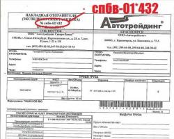
Ready template
Separately, I would like to warn you against putting just anything into a laser printer - if the film is not designed specifically for laser printing, it can melt in the oven and wrap around the shaft, as a result of which you will, at best, end up having to replace the rollers and thermal film. If you really can’t wait, try first to remove the unknown film by placing it between paper sheets and securing everything with construction tape (not film!). If it doesn’t wrinkle and doesn’t stick to the paper, you can use it.

We tear off the polyethylene

The workpiece floats in the bath

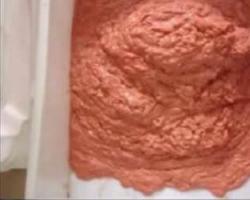
We melt the photoresist

Smooth with a roller

Place the sandwich in a paper box

Pull through the laminator (repeat 3 times!)

Finished workpiece
Next, we prepare a small bath of water, in which we will roll the photoresist onto the board. The bath must be washed first, because dirt, hair and other floating artifacts are contraindicated in our process - where they get in. Next, we cut off the required piece of photoresist and tear off the protective plastic film from the corner. You can pick it up with a needle, but I use sharpened tweezers for SMD components.
Let me note that film photoresist consists of three layers: transparent lavsan, through which illumination is produced, the photoresist itself and a matte polyethylene protective film. So it’s the matte one that needs to be peeled off, don’t get it mixed up.
After the film is torn off, we throw the board into a bath of water, then we press the photoresist film on top of it. Gently press it against the board and smooth it out so that there are no bubbles. Then we take out what we got, put it on a cloth and roll out this sandwich with our finger (preferably with a roller, I use a photo roller) to completely remove the water from under the film. In principle, with some skill, you can roll it “dry”, but firstly, there is no dirt and dust under water (if the bath has been washed), and secondly, due to the stickiness of the photoresist, if the likelihood is that a bubble formed in the center of the board you will not end up It will be possible to remove it either with a roller or a laminator. You cannot tear off the film, so you only have one attempt at dry rolling.
Next, cut a piece of paper with a width slightly larger than the width of the board, and a length slightly longer than twice the length of the board. We fold it in half and put the board into the resulting “daw”. After this, we pull the sandwich through the laminator. You need to stretch it 2-3 times, otherwise the board does not have time to warm up properly. I don’t recommend stretching it without paper - photoresist is a sticky thing and you can’t scrape it off the laminator later.

Everything is ready for illumination

Let's highlight

Side view
We put glass on top of it all for pressing. It is necessary to press, otherwise, due to unevenness, some areas during exposure may blur, become out of focus, and we will end up with a defect. We place the ultraviolet lamp at a height of 20-30 cm above the board. The distance is also important from the point of view of side illumination, since the higher the lamp, the more perpendicular the rays will fall on the template and the less light will pass from the side under the track on the template. Naturally, if you are making a board with a track width of 0.8 mm, these recommendations do not need to be followed. But if you need 0.1 mm, then any little thing can ruin the matter. Next is the lighting. I illuminate it with an 11w lamp for 5 minutes. More powerful lamps will be enough to shine for a significantly shorter time.
In principle, with a good factory template, even prolonged overexposure will not spoil the matter. But if you have a refilled cartridge or the printer produces an insufficiently dense and contrasting pattern, you will have to experiment. If you underexpose, the pattern will be washed off during development; if you overexpose, the pattern will not appear at all or, more often, there will be a coating of indelible photoresist between the tracks, which, when etching the board, will appear as tracks stuck together in a heap.

Dissolving soda ash

We show

Appeared
If you're lucky and everything works out as intended the first time, you should have a beautiful board ready for etching. But everything can go wrong (at least when I started mastering the technology, I made a lot of defects), then the board must be cleaned of the photoresist layer before the next attempt (as well as after etching). You can clean it off with sandpaper, but this is unsporting. It is better to use a solution of any alkali. I happened to have sodium hydroxide lying around, and I wash it off with it, but, for example, Mole, caustic soda and various Mr. Proper agents are quite suitable for cleaning grease from slabs. We lower the board into this solution and after a few minutes the entire photoresist film carefully peels off.

I store it in this tube

Photoresist sticks out of the tube; on the right is a plug from a bag wrapped with electrical tape.
To do this, I use a piece of sewer pipe from the sink, which is sealed tightly on one side, and plugged on the other with a removable plug from a tightly crumpled bag wrapped with electrical tape. It’s also good to transport photoresit in such a tube without fear of crushing it along the way.
Hello dear friends! Now it's time for another article on my blog. Today we will talk about the technology of manufacturing printed circuit boards using film photoresist at home.
There are many different technologies for manufacturing printed circuit boards. There are both completely old-fashioned methods, when printed conductors are formed by cutting through foil, and technologies that are as close as possible to the factory technological process. Typically, printed conductors on PCB are formed by chemical etching.
In my opinion, the most common technology for making printed circuit boards at home is, I once wrote about it on the pages of my blog. Its main advantage is that it does not require any expensive and specific tools and materials. As a rule, everything is within walking distance. Moreover, using LUT technology you can achieve very good results.
The main problem with LUT is that as the area of the printed design increases, the quality begins to steadily decline. This is due to the fact that the pattern created by toner on foil material has a relatively low resolution. It is difficult to form really thin elements of a design with toner. But even if this can be done, such elements adhere very poorly to the surface of copper foil.
When manufacturing printed circuit boards using photoresist, many problems disappear by themselves. Photoresist materials, unlike the toner used in LUTs, were initially created for their subsequent application to various surfaces. Moreover, the surface area does not have a critical important. I have seen from my own experience that photoresist has much higher characteristics such as uniformity of application and quality of adhesion.
But the method of manufacturing circuit boards using the photoresist method also has its drawbacks. The main disadvantage is the inclusion in process additional operations (sticking photoresist, exposure, developing), and this usually scares away beginners. Another disadvantage is that this technology requires the use of additional materials and equipment. You need to find a photoresist, film for making a photomask, etc.
But despite the shortcomings, the photoresist method can produce results that are even higher quality than the results obtained by LUT.
First, we need to prepare a photo template of our future board. For this, some CAD system with the ability to print in negative is suitable, for example Sprint Layout is quite suitable for these purposes. For these purposes I use the Dip Trace program.  As an example, I drew this scarf. Now the board drawing needs to be prepared for printing. To do this, I go to the preview and connect the necessary layers.

Click to enlarge
I'm interested in the following layers: pins, holes, conductors, fill, board. We will not touch the solder mask and marking layers now; in the future they can be used to apply a solder mask and silk-screen printing to the board.
Since my photoresist is negative, I make sure to turn on the “negative” checkbox. Subsequently, when the photoresist is illuminated, the unpainted (unprotected from ultraviolet rays) areas become more resistant to alkaline solutions than the painted areas. With this our photo template has been created, all that remains is to print it.
The photo template file has been created; now it needs to be printed for further use. You need to print the photomask onto film; for these purposes I use Lomond transparent film, matte on one side and glossy on the other. This film is designed for inkjet printers. If you have a laser machine, you can of course try it, but before putting it into the laser machine, try warming the film with an iron. If nothing melts or sticks, then I think it can be used for laser printing. Universal films are also available for sale; they are suitable for both inkjet and laser printers.
One more moment! There is information that when printing on a laser printer it is difficult to achieve the desired density of the pattern. The image should be opaque to UV rays, and apparently the laser designer has problems with this, but this can be dealt with. For these purposes, people use a composition to increase toner density. I will print my photomask on an HP Desk Jet 2130 inkjet printer. We print on the matte side of the film, having first turned off all possible ink saving modes and look at the result 
Now you need to prepare the PCB surface for further work. If, when making boards using LUT technology, it was necessary to clean the surface of the foil with sandpaper, then it is enough to use a tile cleaner and a hard sponge. After this, I wash the board in a soapy solution. 
The surface of the board has been prepared, now it’s time to apply photoresist to the board. My photoresist is negative, film, bought on Aliexpress.  We cut out the photoresist according to the dimensions of our photomask. Now it's time to apply photoresist to the PCB. I found information about two methods of applying photoresist, dry and wet.
In the dry method, the cellophane protective film is gradually removed from the photoresist (usually on the inside of the roll), while at the same time the photoresist is applied to the surface of the PCB and smoothed with a rubber roller. It is very important that there are no air bubbles left.
In my case, I will use the wet method of applying photoresist. To do this, immerse the prepared textolite in cold water. We remove the protective film from the photoresist; for this purpose I use a strip of stationery tape. Next, the photoresist is also lowered into water and applied to the surface of the PCB. Now we take this sandwich out of the water and begin to carefully smooth the photoresist onto the board. You can smooth it with a rubber roller or a plastic card; I use a clean rag for these purposes. In order for the photoresist to set and the quality of adhesion to be even higher, it is very important to pass this sandwich through a laminator. This is how photoresist is rolled into production. I don't have a laminator so I did it as follows.
I wrapped the whole thing in office paper and ironed it two or three times at the lowest temperature.  This is the result I got.
The next stage of photoresist technology is exposure (exposure) of the photoresist. The exposure time is selected experimentally. Timing is very critical when the image density of the photomask is not up to par. I have information about how to choose the right time for exposing the photoresist.
We place our workpiece with the photoresist already applied on the table, place the photomask on top with the image down (where the matte side is) and press the whole thing with glass. There is information that the use of plexiglass is more preferable than, say, window glass, it transmits better ultraviolet rays although I have not verified this information.
I used the lid of a CD box as a pressure glass. Next, I secured the whole thing with paper clips.  This is how the package turned out, the bottom layer of which is textolite with an applied photoresist, followed by a photomask and pressure glass. All that remains is to highlight this whole matter.
We place an exposure installation above this sandwich. My installation is a collective farm one, made, as is usually the case, in a hurry from what was at hand.  In my case, the exposure time will be 4 minutes. So I set the timer on my phone and go have some tea)
Four minutes have passed, now let’s see what happened.  The unexposed areas of the photoresist did not change their color, while the exposed areas turned bright purple. This is the positive side of the indicator photoresist - the quality of illumination can be determined even before etching the board.
Although the unexposed photoresist is not so noticeable, it is on the board and needs to be gotten rid of. And it's very easy to do. After exposure to ultraviolet light, the photoresist becomes resistant to alkaline solutions, but unexposed photoresist still easily dissolves in alkali. The simplest alkaline solution can be prepared from soda ash, especially since it is always within walking distance.  I have soda ash in a package like this, it is sold in hardware stores, wherever they sell household chemicals. Usually located next to washing powders. Yes, and such a pack cost me 60 rubles.
Prepare a solution for developing photoresist. Dissolve a teaspoon of soda ash in a liter of water and stir well. After which we need to immerse our board in this solution. But before doing this, be sure to remove the second protective lavsan film.  To make this procedure easier, the board should be placed in the freezer for 1 minute. Then, using a strip of tape, remove the protective film in one motion. Now you can immerse the board in the developing solution.
In a solution of soda ash, unexposed photoresist dissolves perfectly, but this process can be helped with a soft brush or sponge. The process needs to be constantly monitored, so we periodically remove the board and rinse it under running cold water.  This is the result; here it is very important to make sure that all unnecessary photoresist is gone, otherwise it may interfere with the next stage - etching.

I etch my boards in a ferric chloride solution, the proportions here are simple and intuitive. Usually I take one part FeCL3 to three parts water, but it all depends on the freshness of the solution and the size of the board. If the process drags on, you can add a little more or put it on water bath- this will only speed up the process. You can watch how the printed circuit board is etched forever, but don’t forget to constantly monitor it; we don’t need side etching of the tracks. This is the result.
The board was etched, but the photoresist remained on the surface of the board and covered all the beauty. Photoresist can be removed in various ways. This can be done mechanically, for example with sandpaper or a metal dishwashing sponge. You can use solvents; acetone is perfect for these purposes. But I don't like these options. I won’t thin out the foil layer, and I won’t inhale acetone fumes either.
A “Mole” type pipe cleaning fluid is very suitable for removing photoresist. Pour a little of this liquid into the cuvette and add hot water. After lowering the board into this solution, not even 2 minutes had passed before the entire layer of photoresist separated from the PCB and floated on the surface.
 The basic operations of photoresist technology are completed, all that remains is to drill holes and, if necessary, tin. To drill boards, I use a drill bit from a DPM-type motor; a chuck is mounted on the motor shaft and a button is attached to the body. It is perfect for drilling single-sided boards, but if you need to brighten a board with two layers of foil, a strictly vertical feed of the drill is required. Here you should use a tripod for vertical feeding.
That's the entire technological process of manufacturing printed circuit boards using the photoresist method. In fact, there is nothing complicated here, it is only important to perform all operations consistently.
With a streamlined process, you can get simply magical results. This is not surprising, because in production this is the method used to make boards. There are several points in this technology that have a particularly strong impact on the result; these points need to be carefully monitored.
Well, that's all for me. I hope that this article will be useful to you and that you will find answers to your questions. Be sure to write your questions and comments in the comments. I read all the comments from them and take ideas for new posts.
Friends, be sure to subscribe to blog updates! I wish you good luck and success in achieving all of your goals! See you again!
From n/a Vladimir Vasiliev
What we need:
So, film negative photoresist is a polymer light-sensitive material coated on both sides with a thin protective film (such a sandwich in Fig. 1). Exposure to light either destroys the polymer (positive photoresist), or, conversely, causes its polymerization and reduces its solubility in a special solvent (negative photoresist). During subsequent processing, etching occurs in “windows” formed by illuminated (positive photoresist) or unexposed (negative photoresist) areas of the polymer.
For example, there is a ready-made wiring of a certain device (let it be in):

For making printed circuit board You must first make a photomask for the photoresist. To do this:
We check steps 2-4 again and send the template for printing (see pictures below).
Afterwards, we check our template for transparency - the drawing should be clear and not show through (if everything is visible through it, that’s bad - you can print it again or print a new one (by changing the printer’s print settings))


Here is the result:

In the meantime, while our template is drying (do not leave your fingerprints on it), we will prepare the basis for applying photoresist - PCB foil. To do this, the copper coating of the PCB must be cleaned and degreased: take the PCB of the required size and wipe the copper layer with an eraser to remove dirt from the copper. That's it, you CANNOT touch this part of the PCB with your fingers! To prevent gum particles from remaining on the foil and again to avoid smearing it with greasy hands, the copper should be slightly polished until shiny with paper (but NOT SANDY!).

Next, we take our photoresist (the one that is a roll). We cut off the required piece and hide the roll far away from the light (otherwise, over time it may become illuminated and the whole roll will be lost). You need to pick up the matte protective film a LITTLE (it is located on the inside of the roll, see figure) using a needle, for example.

Do not touch with your fingers the part of the photoresist from which we peel off the film, otherwise it will not stick to the copper.
Now, with a slight movement of your hand, apply the photoresist to the board, press it and gradually remove the matte film (photo). Carefully smooth out the whole thing (the photoresist should stick completely and without bubbles, etc., after smoothing the board can be placed between the pages of a book and pressed tightly)

While we were molding the photoresist to the copper, our photomask had time to dry (hopefully). Now we apply it to the board with photoresist (the side where it is printed, to the photoresist - if you did not print a mirror template). Align the template along the edges of the board and place the glass on it (the template must be pressed tightly to the board, otherwise things that should not be illuminated may be illuminated)
Now we place the ultraviolet lamp at a level of 10-15 cm above the board and expose our photoresist for approximately 7 minutes.
We remove the photomask and peel off the transparent film from the board (photoresist). This operation must be carried out carefully so as not to tear off the photoresist itself from the board.

Now we need to develop our photoresist. To do this, soak our board in a solution of soda ash for 30 seconds. Using light movements of a toothbrush over the surface of the board, we wash off the remaining unexposed photoresist (at the same time, dip the board in a soda solution). When the copper is clearly visible, rinse the board with plain water and let it dry.

What problems might arise?
If photoresist remains where it should not be, it means:
If the tracks themselves are torn off during photoresist development, then:
Well, if the photoresist is completely washed off during development, it means that the UV lamp was underexposed
And then everything is as according to the script: ferric chloride... etching away... washing off the remaining iron... the photoresist can be removed with a knife, or with a solvent (which is much easier), or can be left as a protective coating for the tracks (so to speak).
The first time it may come out a little crooked, but with practice comes mastery. Good luck!